
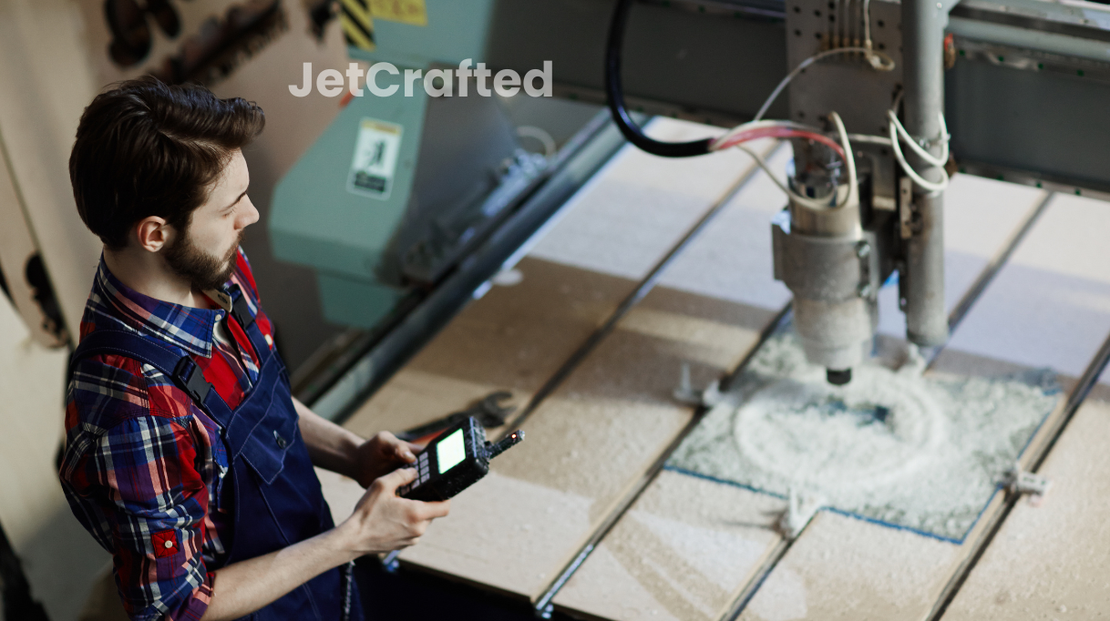
If you’re trying to understand toolpaths, then think of them as GPS directions telling the tool in which direction to go and where to turn. If you enter the wrong directions, you’ll end up getting lost. If CNC machine operators want to achieve the best final results, they need to know how to give the machine accurate coordinates.
The correct CNC toolpaths ensure precision and efficiency in the manufacturing process. So, what is CNC toolpath used for?
When it’s designed correctly, a toolpath can affect the speed, accuracy, and finish of the machined parts. The right toolpath can also reduce material waste and reduce machining time. Whether for drilling, milling, or turning, knowing how to set the right CNC toolpath is indispensable for producing high-quality industrial components.
With an understanding of toolpath strategies, operators can optimize every pass of the cutting tool, guaranteeing parts meet the necessary tolerances and specifications. So, let’s learn all about it.
What is CNC Toolpath?
A CNC toolpath is the route that a cutting tool must follow during the CNC machining process, ensuring it removes material from the workpiece in a controlled and precise manner to form the final product. This path is critical because it directly influences the quality, precision, and efficiency of the machining operation.
Toolpaths for CNC not only dictate the part’s geometry but also affect the cutting conditions, such as the chip load, which is the amount of material that the tool removes with each revolution.
The creation of a CNC toolpath starts with a CAD model, from which the CAM software generates the necessary instructions to guide the cutting tool. These instructions are translated into G-code, the language that CNC machines understand.
The tool then moves along the X, Y, and Z axes, carving out the desired shape from the raw material. An optimized toolpath can decrease the time the tool is in the air (non-productive time) and maximize the cutting time, which improves the overall efficiency of the manufacturing process.
How They Fit With Robot Machining
Robotic arms are now being integrated into the CNC machining processes for their flexibility and ability to handle complex and intricate toolpaths. The programming for robot machining toolpaths requires a high degree of precision to ensure that the robotic arm moves the cutting tool along the intended path.
These toolpaths are generated by advanced CAM programming and direct the movements of the robotic arms, guiding them along the dimensions specified in the CAD model.
Toolpath Types and Terminology
You can’t use CNC machining to produce the parts or components you want without knowing the different types of CNC toolpaths. Let’s go over some of the more common toolpath and their applications.
- Pocketing Toolpaths: They hollow out a region within a workpiece, usually to create a pocket or recess. They’re characterized by their strategic approach to removing material efficiently while maintaining the high-quality surface finish of the surrounding flat areas.
- Constant Stepover. This type of toolpath refers to the consistent distance the tool moves over between passes. It’s best suited for making sure that the finish is even all across the workpiece. The stepover distance can affect the final surface finish. Using a smaller stepover will result in a smoother finish but it will take more time to complete.
- Finishing Toolpaths. These are specifically designed to produce the final surface characteristics of a part. A finish pass is a critical phase where the cutting tool moves along the surface to refine it to the final specifications. These extra passes make it easier to achieve the part’s required tolerances and aesthetic qualities.
- Chamfer and Fillet Toolpaths: They’re used to create angled and rounded edges, respectively. A chamfer is a beveled edge connecting two surfaces, while a fillet is a rounding of an interior or exterior corner.
- Zig-Zag Clearing. A strategy where the tool moves back and forth in a zig-zag pattern to clear large areas of material. This is often used in roughing operations to quickly remove material before finishing.
- Contour Toolpaths. They follow the outline or edge of a part, starting to form the external shape of a component.
- Spiral Toolpaths. They start from a point and spiral outwards or inwards, which is an efficient way to machine circular features.
- Rest Machining. A strategy used to remove the material left by previous larger tools, which cannot reach tighter areas. This ensures that the entire surface is machined uniformly without leaving any uncut areas.
Frequently Used Terms
CNC machining has a specialized language, and CNC-specific terms are used across the industry. This is also true when it comes to CNC toolpaths. Knowing what these terms mean and how they apply to the different types of toolpaths can significantly help you produce even more precise and high-quality CNC machined parts.
To make memorizing this specific jargon easier, we’ve prepared a table with the most common phrases used when discussing CNC toolpaths.
| Term | Definition |
| Toolpath offset | The distance between the programmed toolpath and the actual edge of the finished part. |
| Lead-in and lead-out | Smooth paths that the cutting tool follows to enter and exit the material, preventing sharp corners and tool marks. |
| Cutting depth | The amount of material removed in each pass of the cutting tool. |
| Step over | The distance between adjacent toolpaths. It affects the surface finish and machining time. |
| Tool radius compensation | A software function that adjusts the toolpath based on the actual size of the cutting tool, ensuring accurate cuts. |
| Feed rate | The speed at which the cutting tool moves along the workpiece. |
| Spindle speed | Spindle speed |
| Toolpath verification | Software simulation visualizing and analyzing toolpaths before machining. |
| Toolpath optimization | Refining toolpaths for improved efficiency, surface finish, and tool wear reduction. |
What Affects the Toolpath During CNC Milling?
One of the primary toolpath factors that influence CNC milling is the geometry of the machined part. Complex shapes can require intricate tool movements and multiple toolpath strategies to achieve the desired outcome. Tool engagement, referring to how much of the tool is in contact with the material, also significantly impacts the toolpath.
High engagement can lead to increased tool wear and a greater chance of tool breakage, whereas lower engagement can improve tool life and surface finish but may require more passes to remove the material.
Using smaller cutters is another influential factor as they can navigate tighter spaces and intricate geometries, but they also necessitate more precise and controlled toolpaths.
Additionally, the chosen material and its properties, the rigidity of the machine and workpiece setup, and the cutting conditions, such as speed, feed rate, and coolant use, all play roles in determining the toolpath.

Dynamic Toolpaths Types for CNC Machining Optimization
Dynamic toolpaths generated by advanced CNC toolpath software help further optimize the efficiency and precision of the manufacturing process. These software packages help designers create dynamic toolpaths that adjust the cutting conditions in real-time, responding to the geometric complexity of the workpiece.
Some examples of dynamic toolpaths include:
- Trochoidal Milling: A dynamic toolpath that involves a peeling motion, enabling the tool to cut in a more efficient manner by maintaining a constant chip load.
- Adaptive Clearing: Manages the tool’s engagement with the material, preventing excessive load on the cutter.
- Multi-Axis Dynamic Toolpath: Combines multiple axes of movement for complex machining operations and allows for smooth and efficient machining of intricate parts.
- Hybrid Toolpaths: Combine different dynamic toolpath strategies for specific applications and offer greater flexibility and customization for optimizing machining processes.
To Sum Up: The Right Toolpath
From the initial design phase to the final execution of the piece, each step of creating and applying a CNC toolpath is critical for the success of a project. When you optimize your toolpaths you ensure that the cutting tool operates at peak efficiency. You also reduce wear and tear and allow for precise and accurate shaping of the workpiece.
By carefully considering factors such as tool engagement, cutting depth, and feed rate, operators can develop toolpaths that improve the machining process. In the end, the knowledge of CNC toolpath intricacies not only improves the quality of the final product but also contributes to the overall productivity and cost-effectiveness of the manufacturing operation.
FAQs
1. What is the difference between a 2D and a 3D toolpath?
A 2D toolpath involves movements in two dimensions, usually along the X and Y axes in the XY plane, ideal for flat surfaces or contours. A 3D toolpath adds a Z-axis movement, allowing for complex shapes with varying depths and slopes, suitable for sculpted and 3D surfaces.
2. Can a CNC toolpath be optimized for a better surface finish?
CNC machining toolpaths can be optimized for a better surface finish by adjusting parameters like stepover, feed rate, spindle speed, and tool geometry. Finer stepover distances and slower feed rates often yield smoother finishes but increase machining time.
3. Is simulation software important to toolpath planning?
Simulation software visualizes the toolpath in a virtual environment, allowing for detecting and correcting potential errors, collisions, or inefficiencies before actual machining. This ensures the toolpath is safe and effective, saving time and reducing the risk of costly mistakes.