

TL;DR
- To design parts for CNC machining effectively, you must follow guidelines that account for the material, shape complexity, and machining feasibility.
- You must choose the right materials and design with the machine’s capabilities in mind
- Designing for CNC machining has several restrictions such as tool geometry, material properties, tolerances, wall thickness, etc.
- Different CNC processes, like milling, turning, and drilling follow different CNC design guidelines.
- You can create more durable and cost-effective components by using advanced design techniques.
You must have a solid design when looking at how to design parts for CNC machining. Without a well-thought-out design, you can’t start CNC machining. Designing parts for CNC machining involves following specific guidelines that make the parts you want to make machinable.
These guidelines cover everything from the material selection to the complexity of shapes and the feasibility of producing those shapes using CNC machinery. Your design dictates the feasibility, efficiency, and cost-effectiveness of the machining. Understanding these guidelines is how you can successfully create CNCs.
This article will go over designing parts specifically for CNC machining. By the end, you’ll know what makes a design machinable and how to optimize your designs for the CNC machining process. That way, your projects will move smoothly from concept to completion.
What is The CNC Machining Process?
The CNC machining process is a method used in manufacturing that uses computers to control machine tools. CNC stands for computer numerical control, which means that computers convert a design produced by CAD software into numbers. These numbers can be seen as the coordinates of a graph, guiding the cutting tool to create the desired shape.
Unlike manual machining, which requires operators to control the machines by hand, CNC machining uses technology to automate the movement of machinery parts, including drills, lathes, mills, and grinders. This automation allows for high precision, speed, and efficiency in creating custom parts.
When you look into the design for CNC machining, you’re considering the specifics that make a design suitable for this type of manufacturing. That includes everything from the shape and size of the part to the used material.
Understanding what CNC machining is and its process gives you a better understanding of one of the most fundamental and widely used manufacturing processes, offering unparalleled precision and flexibility in producing different parts.
The Main Restrictions of CNC Design
The design process for this type of machining involves more than imagining the final product. It requires you to know the limitations and capabilities of the CNC machine itself. The design of your final product depends on several factors, including the specific design considerations for CNC machining. These considerations mean your machined parts meet the desired specifications and quality.
Tool Geometry
The shape and size of the cutting tools used in CNC machines determine the features you can machine, including the types of angles, the depth of the cavities, and the overall complexity of the design. For instance, if your design includes sharp internal corners, you might need to revisit it because standard cutting tools have rounded tips.
This limitation means you must plan how to design parts for CNC machining based on the tool’s capabilities, which might involve modifying it to accommodate tool geometry. This consideration is vital for ensuring not only the feasibility of your design but also its dimensional accuracy, as trying to force a design that doesn’t consider tool geometry can lead to parts that fail quality standards.
Tool Access
This is the ability of the cutting tool to reach all areas of the workpiece without obstruction. Complex designs can look good on paper or in a modeling program but be challenging when it comes time to machine them.
For example, designs with deep cavities or undercuts can be difficult, if not impossible, to machine because the tool can’t reach these areas without colliding with other parts of the material or the finished part.
Material Properties
Different materials react in various ways when subjected to the cutting process. You can cut metals like aluminum and brass at higher speeds, which improves production time and reduces costs. On the other hand, hard metals like stainless steel or titanium require slower cutting speeds, more robust tools, and cooling or lubrication methods to achieve the desired outcome.
The choice of material impacts the cutting process and the design considerations for the part. Some designs might be too intricate or delicate for machining out of harder materials without compromising the integrity of the machined parts.
Tolerances
That is the permissible limit of variation in the physical dimension of a machined part. Tolerances are a measure of the precision that the CNC machine can achieve. The tighter the tolerance, the more precise the part must be, which can increase both the time and cost of production.
When designing for CNC machining, know that achieving tight tolerances on every part might be unrealistic or economically unfeasible. Sometimes, it’s best to leave the standard tolerances. In CNC machining, they might range from +/- 0.001 inches (0.025 mm) for precise applications to +/- 0.005 inches (0.127 mm) for more general purposes.
| Process | Tolerance (mm) | Tolerance (in) | Notes |
| CNC Milling | ±0.10 – ±0.25 | ±0.004 – ±0.010 | Tolerance depends on feature size, complexity, and material. Tighter tolerances are achievable with slower machining speeds and smaller tools. |
| CNC Turning | ±0.05 – ±0.15 | ±0.002 – ±0.006 | It has tighter tolerances for diameter than length. Factors include material, spindle speed, and tool type. |
| CNC Drilling | ±0.10 – ±0.20 | ±0.004 – ±0.008 | Hole size significantly impacts achievable tolerance. Smaller holes require higher precision and may have wider tolerances. |
Note: This CNC machining tolerance chart has general guidelines. The actual tolerances will vary depending on the material, the tools, the production volume, and other factors.
Undercuts and Overhangs
An undercut is a recessed area inaccessible to standard CNC cutting tools from the part’s main axis. An overhang refers to a portion of the design that extends beyond a part’s primary form, potentially causing difficulties in supporting the structure during the cutting process.
Both features can complicate machining, requiring special tooling or innovative machining strategies. In some cases, it might be necessary to redesign the part to eliminate undercuts and minimize overhangs to make the machining process more straightforward and cost-effective.
Design Guidelines For CNC Machining
Understanding and implementing CNC machining design guidelines will impact the functionality and manufacturability of your part design. Your designs must be practical, feasible, and cost-effective to produce on a CNC machine. That might seem like a lot to achieve, but it is possible when you follow a few simple rules.
Cavities and Pockets
One of the key points is to avoid very deep cavities, as they pose challenges in machining due to the limited reach of standard cutting tools. Ideally, the depth of any cavity mustn’t exceed four times its width.
This balance helps prevent the tool from flexing or breaking, which can compromise the part’s quality. The standard sizes of cavities and pockets in CNC machining typically range from 1/8” to 1” in depth. Sticking to these sizes can help avoid unnecessary complications during the machining process.
Internal Edges
Due to the nature of the machining process, sharp internal corners can be particularly challenging to create. Instead, the recommendation is to incorporate radii in these areas.
A practical tip is to use a minimum internal radius of 1/3 of the depth of the cavity or feature. That makes your design more machinable and contributes to the structural integrity of the finished part. For example, if you’re designing a slot with a depth of 0.9 inches, aim for an internal radius of at least 0.3 inches.
Wall Thickness
Thin walls can be problematic because they are prone to vibration during machining, causing inaccuracies or even damage to the part. Maintain a minimum wall thickness of 0.8 mm for metals and 1.5 mm for plastics for stability and structural integrity.
However, if your design can accommodate it, thicker walls are preferable. For instance, a wall thickness of 2.5 mm to 3 mm in metals and 3.5 mm to 4 mm in plastics is ideal for most applications. These thicknesses strike a good balance between strength and the ability to remove material efficiently.
Different materials can tolerate varying wall thicknesses, so below is a table overview with some general dimensions:
| Material | Recommended Wall Thickness (mm) | Feasible Wall Thickness (mm) | Comment |
| Aluminum | 1.0 – 2.0 | 0.5 – 1.0 | It depends on the alloy and application. Thinner walls are possible with careful design and smaller tools. |
| Steel | 1.5 – 3.0 | 1.0 – 2.0 | Similar to aluminum, consider alloy and application. Thinner walls are possible for higher-strength steel. |
| Brass | 1.0 – 2.0 | 0.75 – 1.5 | Ductile material that allows for slightly thinner walls compared to steel. |
| Titanium | 1.0 – 1.5 | 0.75 – 1.25 | High strength-to-weight ratio. It allows for thinner walls but requires specialized tooling. |
| Stainless Steel | 2.0 – 3.0 | 1.0 – 2.5 | Consider the specific alloy for machinability and strength |
| Acrylic | 3.0 – 4.0 | 2.0 – 3.0 | A brittle material that requires thicker walls to avoid cracking during machining. |
| Polycarbonate | 2.0 – 3.0 | 1.5 – 2.5 | More flexible than acrylic. It allows slightly thinner walls. |
| ABS | 1.5 – 2.5 | 1.0 – 2.0 | A common thermoplastic. It has a good balance of strength and machinability. |
| Wood | 4.0 – 8.0 | 3.0 – 6.0 | Depends on the wood type and grain orientation. Thinner walls are possible with laminates or specific joinery techniques. |
Holes
The best practice when designing holes is maintaining standard diameters corresponding to common tool sizes. That simplifies the machining process and reduces production time.

When it comes to depth, try to limit the depth of a hole to four times its diameter. This limitation prevents tool deflection and breakage, ensuring the holes are accurately machined. Consider using a pilot hole to guide the drill and reduce the risk of deviation for deeper holes.
Threads
When designing internal threads, do it with standard sizes in mind. Including a slight chamfer at the beginning of the thread to facilitate the start of a tap or die can also be beneficial. Allow enough space for the tap to start properly, which means enlarging the hole diameter at the start of the thread.
External threads, on the other hand, should have a generous thread allowance for machining to achieve the desired thread profile. Standard thread sizes and pitches can significantly simplify the machining process and lower costs.
Small Features
Thin walls, sharp internal corners, and minuscule holes may be difficult or impossible to machine accurately. To navigate this, try to design with the largest features possible that still meet the requirements of your part.
For example, if your design includes small holes, ensure they are at least 1 mm in diameter to accommodate standard drill sizes. Likewise, aim for internal radii to be at least 1 mm to avoid using specialized tools.
Text and Lettering
Text should be carved with a minimum character height of 2 mm so it’s legible after machining. Avoid using fonts with finer details or serifs, as these can be difficult to reproduce accurately with a cutting tool. Instead, opt for simpler, sans-serif fonts and ensure enough space between characters to prevent them from merging during the machining process.
What Design Features to Avoid for CNC Machining
During CNC machining, some design features can spell trouble, either by negatively affecting the final product or being downright unfeasible for machining. Knowing what to avoid is as essential as knowing what to include. That is where a good design guide will show you how to design parts for CNC machining the correct way.
Machine shops often see designs that don’t follow these best practices, leading to increased costs, delays, and a product that doesn’t meet expectations. By adhering to a CNC machining design guide, you get smoother operations and a better result. Design elements to avoid include:
- Pockets That Are Too Deep – Deep pockets require long cutting tools, which can introduce vibration and reduce accuracy. A rule of thumb is to keep pocket depths to four times the width of the pocket. For instance, if you’re designing a pocket 0.25 inches wide, try not to make it deeper than 1 inch.
- Regions That Are Too Narrow – No matter how precise CNC machines are, they can’t machine areas they can’t reach. Narrow regions can also lead to the tool using too much force on a small area, potentially causing damage to both the material and the tool.
- Internal Corners That Are Too Sharp – Any internal corner in your design will have a radius determined by the tool’s radius. Not accounting for this can lead to parts that don’t fit together as intended or require manual finishing, which is time-consuming and brings additional costs. A practical example is designing a square peg to fit into a square hole. If you design the internal corners of the hole perfectly sharp, the peg won’t fit unless the corners of the peg are also round to match the radius of the tool used for the hole.
- Inaccessible Features – If you design a feature that the tool cannot access, this part of your design cannot be machined, leading to a product that doesn’t meet your specifications. For example, a deep, narrow pocket might seem like a necessary part of your design, but the milling tool can’t make it, if it can’t reach the bottom of this pocket. To fix this, you can make the pocket wider or shallow so the tool can reach.
- Filleting Outside Edges – Fillets can reduce stress concentrations in certain parts but pose challenges in CNC machining when applied to outside edges. The tool path required to create a fillet on an outside edge can be complex and time-consuming, which might affect the final product’s quality and increase production costs. Instead, consider chamfering the outside edges. Chamfering involves cutting a symmetrical sloping surface at an edge, and it’s much simpler for CNC machines to produce.
- Walls That Are Too Thin – It may seem like a way to save material or reduce weight, but thin walls can lack the necessary strength and may not be machinable. The vibration of the CNC machine‘s tools can cause thin walls to flex or even break, ruining the part.
- Holes With Flat Bottoms – Standard CNC tools create holes rounded at the bottom, so designing a hole with a flat bottom requires special tools and additional machining steps, increasing the complexity and cost of production. Instead, if your design can accommodate it, plan for holes that are completely through the part or have the standard round bottom. If a flat-bottomed hole is necessary, consider adjusting your design to include a post-machining process to finish the hole to the desired specification.
Design Tips for CNC Milling
When designing parts for CNC milling, you have to consider the limitations and capabilities of the machine. Your design decisions can significantly affect product cost and functionality. Keeping a few critical design tips in mind can streamline the production process and yield better results.
No Sharp Angles
One of the limitations of CNC milling is its inability to create perfectly sharp internal corners. That is due to the round shape of the milling cutter, which cannot produce a 90-degree angle inside a pocket or hole. Trying to achieve sharp internal corners can lead to increased production time and higher costs, as it might require specialized tools or additional finishing processes.
A practical solution is to design internal corners with a radius. That makes the parts easy and cheap to manufacture and adds to the structural integrity, reducing stress concentrations in those areas. If your design requires sharp internal corners, consider adding a relief or using a smaller tool for those areas, though this might increase your production costs.
No Deep Narrow Slots
Creating deep and narrow slots during the CNC milling process poses challenges, including tool deflection, excessive tool wear, and difficulty in chip evacuation. These issues can compromise the dimensional accuracy of the slot and affect the part’s quality. It’s advisable to avoid designing deep slots compared to their width to mitigate these problems.
If your design needs a deep slot, consider using a stepped design approach, where the slot is made wider at the bottom or designed in increments of depth, allowing the tool to clear out chips more efficiently and reduce wear.
Use The Large Internal Radii
Larger radii reduce the stress on the milling cutter and improve the surface finish of the milled part. This design choice also improves the part’s strength by distributing stress evenly across the area, making it less prone to cracking or breaking under load. Opt for generous internal radii in your designs to facilitate a smoother milling process and create more durable parts.
Design Tips for CNC Turning
How the machine removes material varies significantly from one CNC machining technique to another. CNC turning, which involves rotating the workpiece while a cutting tool moves in a linear path, requires different considerations from those of CNC milling, where the tool rotates instead.
Don’t Design Sharp Internal and External Corners
The cutting tools used in CNC turning are round, making it challenging to achieve perfectly sharp corners. Instead, adding fillets (rounded corners) into your design can significantly improve manufacturability.
For internal corners, adding a radius of at least one-third the depth of the cavity can prevent tool deflection and ensure smoother, more accurate cuts. External corners also benefit from fillets to reduce the risk of chipping and give a higher-quality finish.
Don’t Design Long, Thin Parts
Due to vibration issues, if your design requires length, consider adding ribs or gussets to increase rigidity without significantly increasing weight or material cost. This will maintain the desired precision throughout the machining process.
Include Feature Symmetry In the Design
Symmetrical parts can be balanced and positioned more easily on the CNC turning center, which can lead to faster production times and higher-quality finishes. That doesn’t mean every part must be perfectly symmetrical, but you should strive for balance in the design for more efficient CNC turning. Evenly distributing the mass and thoughtful placement of features can minimize complications during the machining process.
Design Tips for CNC Drilling
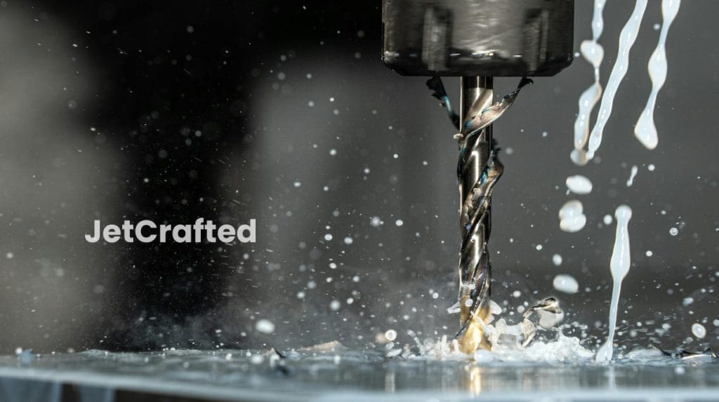
CNC drilling is a process separate from CNC milling or turning and follows other design guidelines. It requires a specialized approach, focusing on creating clean, accurate holes in a piece of material.
Include Appropriate Hole Depth
Generally, the depth of a hole should not exceed ten times its diameter. This guideline helps prevent tool breakage and maintains the hole’s integrity. Deep holes can lead to issues with chip removal and may require special tools or techniques, such as peck drilling, to achieve the desired outcome without compromising the quality of the workpiece.
Don’t Incorporate Partial Holes
Partial holes can lead to inaccuracies in the drilling process, as the drill bit may wander or deflect when it does not have a solid surface to start on. That can result in holes that are not perfectly round or are out of position, which can be a significant issue for parts requiring high precision.
Aim for complete holes that fully penetrate the workpiece or stop at a predefined depth, to get a precise outcome. If a design necessitates a partial hole, consider adjusting the design to include a full hole or use a different machining process.
Keep the Drill Axis And Surface Perpendicular
An angled drill can cause oval-shaped holes and uneven hole sizes. It can even damage the surface of the material. To avoid these problems, always design your parts so the drill can access all holes in a perpendicular alignment.
Don’t Drill Through Cavities
This action can cause the drill bit to wander or deflect, resulting in inaccurate hole placement, and can damage the tool and workpiece. If your design requires drilling near a cavity, see if you can add a material to stabilize the area during the drilling process. This will maintain precision while protecting the integrity of your workpiece.
If you want the best quality parts or finished projects, JetCrafted’s CNC drilling services follow your exact specifications and always give you a high-quality product.
Advanced CNC Machining Design Strategies
Using more advanced CNC design strategies allows you to tackle more complex projects. One such strategy is to use Electrical Discharge Machining (EDM). This process can make complex features challenging to achieve with other machining methods. It uses electrical sparks to mold materials into your desired shape.
Implementing post-machining processes can also improve the quality and functionality of your designs. These processes, which include treatments like anodizing, heat treating, and painting, improve your project’s aesthetics and make the finished product more durable.
Another part of advanced CNC machining design is achieving precision through tolerance management. Properly adjusting the tolerances for your project can make the difference between a part that fits perfectly and one that doesn’t work at all. Tight tolerance levels allow for higher precision, which is vital for making components that interact with other parts. By mastering tolerance management, every piece you create will meet the exact specifications and maximize efficiency in the work process.
The Final Design
Understanding how to design parts for CNC machining is crucial for the success of your projects. By focusing on the key aspects discussed in this article – such as considering material selection, tolerances, and the geometry of your designs – you can improve the manufacturability and functionality of your parts.
When you learn design principles specific to CNC machining, you can tailor your approach to meet the unique demands of any manufacturing process. Following these design guidelines streamlines the production process and improves the overall quality of the final product.
FAQs
1. Does material choice affect CNC machining?
Different materials behave uniquely when machined, affecting the speed, tool wear, and quality of the finished product. For example, metals like aluminum are easier to machine than stainless steel, leading to faster production times and lower costs. The material helps your part meet the desired specifications without unnecessary expense or difficulty in machining.
2. Why do tolerances matter in CNC machining?
Tight tolerances mean parts have minimal differences from the intended design, which is crucial for assemblies that need precision. If tolerances are too loose, parts might not function as intended, leading to failure in the system. Achieving the right balance in tolerances is vital for precision, part functionality, reliability, and cost-effectiveness.
3. Can I lower the cost of CNC machining without compromising quality?
You can achieve that by optimizing your design for manufacturing. Simplifying part geometry, reducing the number of complex features, and selecting a more easily machinable material can decrease machining time and tool wear, thus reducing costs. Also, consider batch production to take advantage of economies of scale.
4. Can post-machining processes improve CNC machined parts?
Post-machining processes, such as heat treatments, coatings, and surface finishes, can significantly improve the performance and appearance of CNC machined parts. These processes can increase hardness, better corrosion resistance, or improve surface smoothness. While they add to the production time and cost, their benefits often justify the investment.
5. How do I choose the right finish for my CNC machined part?
Choosing the right finish for your CNC-machined part depends on the part’s intended use, required appearance, and durability. If the part is exposed to harsh conditions, a finish that adds corrosion resistance might be the best option. For parts that need to look good, a visually appealing finish, like anodizing, could be ideal. Consider functionality, environment, and budget when selecting a finish to ensure it meets all your requirements.